60-years-of-experience

60+ Years of Experience

satisfaction-guarantee

Satisfaction Guarantee

short-lead-times

Short Lead Times

SMT vs. THT in PCB Assembly: Which is Best?

Every failed PCB build has an origin point. Most engineers assume it’s a manufacturing defect, a bad component batch, or a soldering error. But the most expensive, preventable failures trace back to a single decision made before production ever started: the choice between surface mount technology (SMT) vs through-hole technology (THT).

Here’s what most suppliers won’t tell you upfront: these two technologies are not interchangeable. They perform differently under stress, have different cost structures at scale, and behave differently within the real-world operating environments your product will actually face, whether that’s a surgical suite, a military vehicle, or an industrial control panel.

The dangerous part? It often looks fine on paper until it doesn’t.

Understanding the real difference between SMT and through-hole isn’t just technical due diligence. It’s the foundation of every reliable, cost-efficient, field-proven PCB build.

Here’s what you need to know before your next project goes to production.

Key Takeaways:

  • SMT and THT are not interchangeable: Choosing the wrong technology causes field failures, rework costs, and compliance issues that no QA process will catch in time.
  • Your operating environment is the deciding factor: Vibration, heat, stress, and regulatory requirements determine which technology your board actually needs, not personal preference or vendor convenience.
  • Most high-performance boards use both: Mixed-technology assembly combines SMT’s density with through-hole’s mechanical strength and requires a manufacturer who can execute both flawlessly.
  • Your manufacturer’s capabilities matter as much as your design: A shop limited to one technology will fit your design to their process, while the right partner fits their process to your design.

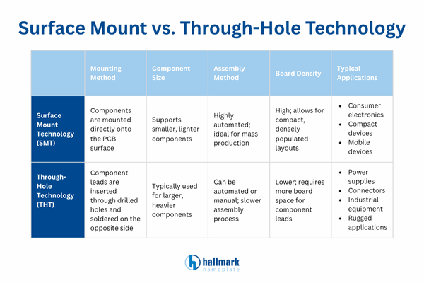
What Is SMT & Why Engineers Love It

Surface mount technology (SMT) is the dominant PCB assembly method in modern electronics. Components mount directly onto the surface of the board, with no drilling required.


smt (surface mount technology)

This makes SMT ideal for high-density, compact designs where space and weight matter.

Here’s what makes SMT stand out vs THT:

  • Smaller component footprint enables tighter, more complex circuit designs
  • Faster automated assembly means lower labor costs and shorter lead times
  • Components can be placed on both sides of the board
  • Superior high-frequency performance due to shorter electrical paths

SMT is the go-to for electronics where miniaturization is non-negotiable, think medical devices, telecommunications equipment, and compact industrial controllers.

The SMT Advantage: Speed, Scale, and Precision

Let’s talk numbers. SMT assemblies can achieve component placement rates of tens of thousands of components per hour using automated pick-and-place machines. That’s not just efficiency — it’s a competitive advantage.

At scale, SMT dramatically reduces your per-unit cost, which directly impacts your product’s margin and your ability to win competitive bids. For buyers in the computer & IT, food service, and telecommunications sectors, where product cycles are fast and volumes are high, SMT is typically the right foundation.

Through-Hole Isn’t Dead, Far From It

Here’s the truth most suppliers won’t tell you: through-hole technology (THT) still dominates in high-stress, high-stakes applications. Components in THT are inserted through drilled holes and soldered on the opposite side of the board, creating a mechanical bond that’s extraordinarily robust.

When through-hole is the smarter choice:

  • Applications exposed to extreme heat, vibration, or mechanical stress
  • Military and aerospace environments where component failure isn’t an option
  • High-power connectors, transformers, and capacitors require superior anchoring
  • Prototype and low-volume runs where manual assembly is more cost-effective

The reality? If your product operates on a jet, in a surgical suite, or on a factory floor, through-hole reliability often justifies every penny of the additional cost.

smt vs tht

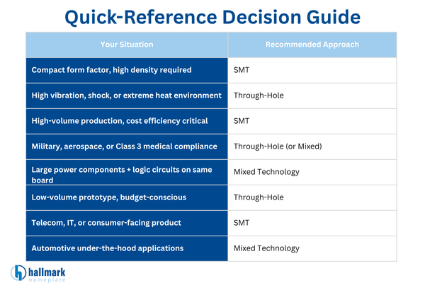
SMT vs THT: Which Technology Is Right for You?

Before you spec a single component, answer these five questions honestly. Your answers will tell you nearly everything you need to know.

1. What environment will this board operate in?

This is the most critical factor. SMT performs reliably in standard operating environments, controlled temperatures, minimal vibration, and predictable stress. But the moment your board faces extreme heat cycles, constant mechanical shock, or high humidity, the through-hole’s superior mechanical bond becomes non-negotiable.

If your product operates in aerospace, defense, or heavy industrial settings, through-hole on structural components is not optional; it’s mandatory.

2. How much board real estate do you have?

Space-constrained designs, wearable medical devices, compact control panels, and telecommunications equipment demand SMT. You simply cannot achieve the same component density with through-hole.

If size and weight are primary design constraints, SMT wins. Full stop.

3. What is your production volume?

This is where budget and technology intersect. SMT’s automated pick-and-place assembly scales beautifully; the more units you run, the lower your per-unit cost drops. Through-hole relies heavily on manual assembly and soldering, which keeps labor costs elevated regardless of volume.

For prototype and low-volume runs under 500 units, through-hole is often more cost-efficient. For mid-to-high volume production, SMT delivers the margin advantage.

4. What are your compliance and certification requirements?

Certain industries carry non-negotiable standards. Military and defense contracts frequently reference MIL-STD-810 for environmental stress. Medical devices often require IPC-A-610 Class 3 workmanship standards. Aerospace applications demand rigorous thermal and vibration performance documentation.

Through-holes’ mechanical resilience typically makes it easier to satisfy the most demanding certification thresholds, particularly where solder joint integrity is tested under sustained stress.

5. Does your design include high-power components?

Power transformers, large capacitors, high-current connectors, and relays generate significant heat and mechanical force during operation. SMT solder joints are not engineered to anchor these forces long-term. Through-holes’ physical insertion into the board substrate provides the structural support these components demand.

If your design includes heavy power components alongside signal processing logic, you’re almost certainly looking at a mixed-technology board.

Why Mixed Technology Is Sometimes Best

Here’s where most engineers oversimplify the decision. Many high-performance boards don’t choose one or the other. They use both.

Mixed-technology PCB assembly combines SMT’s density and speed with through-hole’s mechanical strength exactly where it’s needed. Precision connectors, power components, and structural anchors use through-hole. Signal processing, logic, and microcontrollers use SMT.

This hybrid approach is increasingly common in:

  • Medical devices requiring a compact form with reliable connections
  • Military electronics that need dense logic circuits and ruggedized power interfaces
  • Industrial controls with membrane switches or control panels integrated into the assembly

The key is having a manufacturer who can execute both flawlessly, in-house.

smt vs tht quick reference guide


The Hidden Variable: Your Manufacturer’s Capabilities

You can have the perfect PCB design on paper. But if your manufacturer can’t execute both technologies with precision, or forces you to work around their limitations, then you’re already at a disadvantage.

What to look for in an electronic assembly partner:

  • Demonstrated experience with both SMT and through-hole processes
  • IPC-compliant quality standards and documented quality control processes
  • U.S.-based manufacturing (especially critical for military and aerospace compliance)
  • Hands-on engineering and design support, not just a quoting portal
  • Ability to scale from prototype to production without switching vendors

This is not a standard procurement decision. The wrong partner costs you in rework, delays, and failed inspections.

Choose the Right Partner for Your PCB Assembly

Now you understand the real difference between SMT vs THT and why the most sophisticated PCB builds use both strategically. The technology you select needs to match your environment, your volume, your compliance requirements, and your performance specifications. Don’t let budget pressure push you toward the wrong method, and don’t let a vendor’s limited capabilities define your design.

Ready to get your PCB assembly right the first time?

At Hallmark Nameplate, we’ve been engineering and assembling precision electronics for clients in aerospace, military, medical, and industrial sectors since 1957. Our U.S.-based team provides hands-on design support, full SMT and THT capability, and the quality certifications your project demands. Whether you’re in prototyping or scaling to full production, we deliver boards that perform exactly as specified.

Don’t leave your next PCB build to chance. Partner with a manufacturer who’s been getting it right for over six decades.

Request a quote or get a free sample box today!

Want to learn more? Read our complete guide to PCBs and electronic assembly.

Exploring Membrane Switch Uses Across Different Industries

Every engineer and purchasing agent specifying a control interface faces the same question: Will this component survive the field, pass certification, and ship on schedule?

Membrane switches answer all three, which is why they’re embedded in medical devices, defense systems, industrial controls, and automotive platforms worldwide.

Below, you’ll see where membrane switch uses dominate across six industries, the compliance and performance demands in each, and what separates a production-ready supplier from a costly sourcing mistake.

Key Takeaways:

  • Six industries rely on membrane switches – Consumer electronics, medical, fitness, industrial, automotive, and defense rely on membrane switches for sealed, durable, low-profile control interfaces.
  • Compliance drives supplier choice – Medical requires ISO 13485, defense requires ITAR, and industrial demands ISO 9001 + UL
  • Reliability beats aesthetics – Engineers spec membrane switches for IP-rated sealing, tactile feedback, and field durability
  • U.S. manufacturing reduces risk – Domestic sourcing cuts tariffs, shortens lead times, and protects certification timelines.

Why Membrane Switch Uses Span So Many Industries

Here’s the thing most buyers miss: a membrane switch isn’t just a button replacement; it’s a sealed user interface that consolidates multiple components into a single, thin, reliable stack.

That matters because engineers and purchasing agents face three constants: shrinking form factors, tightening compliance, and zero tolerance for field failures. Membrane switch applications solve all three at once.

Their low-profile design, IP-rated sealing, and customizable graphic overlays make them ideal for any environment where dust, moisture, chemicals, or heavy use would destroy mechanical switches. Add ITAR-compliant sourcing and medical-grade materials, and the use cases multiply fast.

Top Applications of Membrane Switches

Membrane switches aren’t a niche component; they’re the default control interface across every industry where reliability, compliance, and durability matter more than flash.

Below, we break down the six sectors where membrane switch uses dominate, what engineers prioritize in each, and why the stakes make supplier selection a critical decision rather than a commodity purchase.

Hallmark Nameplate infographic showing six membrane switch applications across consumer electronics, fitness, medical, automotive, military, and industrial industries

1. Consumer Electronics: The Membrane Switches You Touch Daily

Look around your kitchen right now. Your microwave panel, coffee maker keypad, and air conditioner controls almost certainly run on membrane switches.

Manufacturers love them for two reasons: they’re cheap to produce at scale and nearly impossible to damage through normal use. Spill-proof, dust-sealed, and flush-mounted, they wipe clean in seconds and survive a decade of daily presses.

TV remotes, home security panels, smart thermostats, and gaming peripherals all rely on the same principle. The graphic overlay takes the abuse, the circuit layer stays protected, and the device keeps working long after a mechanical alternative would have failed.

what are membrane switches and uses, Person pressing membrane switch buttons on a microwave control panel showing consumer electronics application

2. Fitness and Gym Equipment: Built for Sweat, Built for Reps

Walk into any commercial gym, and you’ll see membrane switches taking a beating. Treadmill consoles, elliptical displays, rowing machine controls, all sealed to survive sweat, spilled water bottles, and 80+ hours of weekly use.

Mechanical buttons would corrode and stick within months. Custom membrane switches shrug it off because the circuit layer sits beneath a chemically resistant polyester overlay.

And here’s what fitness OEMs really care about: service call costs. A single console failure at a 24-hour gym triggers downtime, user complaints, and an expensive field repair. Sealed membrane interfaces cut that rate dramatically.

Life Fitness exercise equipment membrane switch keypad and display showing fitness industry application for gym equipment controls

3. Medical Equipment: Where Membrane Switches Save Lives

Now consider the stakes in a hospital. A contaminated control panel isn’t an inconvenience; it’s a patient safety event.

That’s why diagnostic instruments, patient monitoring systems, infusion pumps, and laboratory analyzers lean heavily on medical membrane switches. The sealed surface resists disinfectants, prevents bacterial ingress, and meets the stringent requirements of ISO 13485.

Precision matters here, too. Tactile feedback tells a nurse the button registered without needing to look, reducing errors during high-pressure moments.

Here’s the kicker: medical OEMs rarely switch suppliers once a device is validated. Choosing a U.S.-based, ISO 13485-certified manufacturer the first time isn’t overkill; it’s risk mitigation that protects your FDA submission timeline.

4. Automotive: Low-Profile, High-Vibration, Zero Compromise

Automotive dashboard membrane switch controls for HVAC and infotainment showing low-profile vehicle interface design

Automotive dashboards, HVAC controls, infotainment trim, and commercial vehicle panels all lean on membrane switches for one simple reason: they don’t rattle, they don’t wear out, and they survive temperature extremes from -40°F to 185°F.

Weight matters too. Every gram removed from a vehicle interior improves fuel efficiency, and membrane switches weigh a fraction of traditional button assemblies.

Add customizable backlighting, branded graphic overlays, and aggressive cost-per-unit targets, and you see why Tier 1 automotive suppliers specify them across passenger, commercial, and off-highway vehicles.

5. Military and Defense: ITAR-Compliant and Battlefield-Ready

Let’s be blunt: defense applications are unforgiving. A switch failure on a battlefield communication system, targeting interface, or vehicle control panel isn’t a warranty claim; it’s a mission failure.

That’s why military membrane switches are engineered to survive MIL-spec conditions: sand, saltwater, shock, extreme altitude, and chemical exposure. Rugged overlays, shielded circuitry, and NVIS-compatible backlighting meet the brutal requirements of modern defense platforms.

And for U.S. defense contractors, ITAR registration isn’t optional; it’s a gate. Hallmark Nameplate is ITAR-registered, meaning cleared engineers, secured supply chains, and full compliance with export-controlled programs.

6. Industrial Control Panels: The Harsh Environment Specialist

Industrial control panel with emergency stop and push button membrane switches for harsh environment machinery

Step onto any factory floor, and the environment turns hostile. Dust, oil mist, cleaning solvents, vibration, temperature swings, all enemies of traditional switches.

Industrial membrane switches thrive here because they’re built for exactly these conditions. IP65 and IP67 sealing ratings keep contaminants out, while embossed tactile keys give operators confirmation even through gloves.

Picture this: a food processing plant washing down a control panel with high-pressure sanitizer every shift. A membrane interface handles it. A keypad with gaps between keys doesn’t.

That durability translates directly to uptime, which is the only KPI that matters in manufacturing.

The Common Thread Across Membrane Switch Uses

Notice what every industry above has in common? Across all six membrane switch uses, the pattern is the same: reliability, compliance, and customization, not aesthetics.

Buyers don’t choose membrane switches because they look sleek. They choose them because the switch survives the environment, meets the certification, and ships on time.

Lose any one of those three, and the project stalls. That’s why selecting a domestic, multi-certified membrane switch manufacturer matters more than shaving a few cents per unit from an overseas supplier.

Membrane Switch FAQs

Why are membrane switches used in medical devices?

Medical membrane switches are often specified for diagnostic instruments, patient monitoring systems, infusion pumps, and laboratory analyzers because the sealed surface can help resist hospital-grade disinfectants, reduce bacterial ingress risk, and support ISO 13485-aligned manufacturing requirements.

Tactile feedback also reduces operator error during high-pressure clinical moments. Because changing suppliers after device validation can create additional documentation, testing, and approval requirements, selecting a U.S.-based, ISO 13485-certified manufacturer from the start can help reduce risk.

What certifications are required for military and defense membrane switches?

For export-controlled U.S. military and defense programs, membrane switch manufacturers may need ITAR registration, U.S.-based personnel handling controlled technical data, secured supply chains, and compliance with export-control requirements.

Military-grade membrane switches are also engineered to MIL-STD-810 environmental conditions, including sand, saltwater, shock, extreme altitude, and chemical exposure. Additional features like NVIS-compatible backlighting and shielded circuitry are standard for modern defense platforms.

What sealing ratings do industrial membrane switches need?

Industrial membrane switches typically require IP65 or IP67 sealing ratings to keep dust, oil mist, cleaning solvents, and high-pressure sanitizers out of the circuit layer.

IP65-rated membrane switches are protected against dust and low-pressure water jets, while IP67-rated membrane switches can withstand temporary submersion. Embossed tactile keys are also specified so operators can confirm button presses through gloves. These ratings are essential for food processing plants, manufacturing floors, and other harsh industrial environments.

What industries use membrane switches?

Membrane switch uses span six major industries: consumer electronics (microwaves, coffee makers, thermostats), fitness and gym equipment (treadmill consoles, rowing machines), medical equipment (diagnostic instruments, patient monitors, infusion pumps), automotive (dashboards, HVAC controls, infotainment), military and defense (communication systems, targeting interfaces, vehicle control panels), and industrial control panels (factory machinery, food processing equipment).

Each industry may select membrane switches for reliability, compliance, and durability requirements that can be difficult to meet with traditional mechanical switches.

How do membrane switches differ from mechanical switches?

Membrane switches are flat, sealed user interfaces that collapse multiple components into one thin, reliable stack, while mechanical buttons have physical gaps, moving parts, and multiple failure points.

Membrane switches offer IP-rated sealing against dust, moisture, and chemicals, weigh significantly less than mechanical assemblies, survive a decade of daily use, and support customizable graphic overlays, backlighting, and branded aesthetics. Mechanical switches corrode, stick, and fail in harsh environments like gyms, factories, and medical facilities.

Why does U.S. manufacturing matter when sourcing membrane switches?

U.S.-based membrane switch manufacturing can support shorter lead times, clearer communication, stronger intellectual property protection, and reduced exposure to import tariffs on finished goods.

Tariffs, geopolitical disruptions, and ITAR export restrictions can make offshore sourcing more challenging for manufacturers serving regulated medical, defense, aerospace, and industrial markets. For defense programs specifically, ITAR registration requires U.S. manufacturing with cleared engineering personnel.

Does Hallmark Nameplate manufacture custom membrane switches?

Yes. Hallmark Nameplate designs and manufactures custom membrane switches for aerospace, medical, defense, and industrial OEM customers. The company was founded in 1957 and holds ISO 9001:2015, ISO 13485:2016, ITAR registration, UL Listed, RoHS compliance, and 3M Preferred Converter certifications. All manufacturing is performed at the Mt. Dora, Florida, facility, with full U.S.-based engineering support and secured supply chains for export-controlled programs.

Get High-Quality Membrane Switches for Any Application

So whether you’re designing a medical monitor, a factory control panel, or a defense-grade interface, the membrane switch inside your product determines whether it ships, certifies, and survives the field.

Now here’s the real question: is your current supplier built to handle your industry’s specific demands, or are you one failed audit, one botched certification, or one missed deadline away from rebuilding your supply chain?

Request a free sample box from Hallmark Nameplate and see, feel, and test U.S.-built membrane switches engineered for your industry, backed by ISO 9001, ISO 13485, ITAR, and UL certifications, and nearly seventy years of American manufacturing.

Want to learn more? Read our complete guide, Everything You Need to Know About Membrane Switches.

Printed Circuit Board Repair: 7 Reasons Your PCB Isn’t Working

Printed Circuit Boards (PCBs) are the backbone of modern electronics, containing intricate networks of electrical connections that enable devices, from cell phones to computers, to function smoothly. However, circuit board repair techniques are rarely considered when you buy a piece of technology.

Unfortunately, these crucial PCB components are not immune to damage. When one fails, it can be a frustrating and costly experience for businesses and individuals alike. The good thing is that repairing a PCB is often a viable solution that can save you both time and money.

In this blog, we will delve into the world of printed circuit board repair, exploring the various types of damage that can occur and the tools and techniques used for repair. Whether you’re a professional electronics technician or a hobbyist, this guide will provide you with valuable insights into the specialty of circuit board repair.

Key Takeaways:

  • PCB failures often result from physical damage, component failure, or design and manufacturing defects.
  • Common issues include plating voids, thermal voids, acid traps, and insufficient copper-to-edge clearance.
  • Proper troubleshooting, such as inspecting for damage and testing components, can help identify root causes quickly.
  • Partnering with a trusted PCB manufacturer like Hallmark Nameplate ensures high-quality design, testing, and long-lasting performance.

7 Reasons Your Circuit Board Isn’t Working

According to KPI Depot, the average failure rate for consumer electronics is around 2.5%, meaning even minor defects in a PCB can have noticeable impacts on device performance and reliability.

A malfunctioning device often points to issues with its printed circuit board. Even small defects or design flaws can disrupt performance or cause complete failure. Understanding the common causes of PCB problems is the first step toward effective troubleshooting and repair.

reasons your pcb isn't working

1.) Physical Damage

A printed circuit board contains conductive pathways etched onto its surface. These pathways carry signals and power between electronic components mounted on the board. Physical damage to a PCB can cause it to stop working by interrupting these conductive pathways or damaging the electronic components.

For example, if the board is bent or cracked, it can cause the pathways to break or become disconnected from the components. Similarly, exposure to moisture, heat, or chemicals can corrode or damage the conductive pathways or the components themselves.

Excessive vibration or shock can also dislodge components or cause them to break loose from the board, disrupting the circuit’s operation. This is why it is important to handle and store PCBs carefully to avoid physical damage and ensure their longevity.

2.) Component Failure

There are a few common components of a circuit board that we should differentiate.

  • Batteries provide a source of electrical power.
  • Capacitors store electrical charge to ensure even distribution.
  • Copper traces are the embedded copper pathways on a board that facilitate the flow of electrical current.
  • Diodes control the direction of electrical current.
  • Inductors store electrical current as an electromagnetic field.
  • Light-emitting diodes (LEDs) enable one-way current flow and light up when there is current present.
  • Resistors slow down the electrical current.
  • Switches can allow or block the flow of current depending on whether they are open or closed.
  • Transistors amplify the electrical charge.

A failure of any of these components can cause the PCB to stop working. Electronic components are susceptible to a variety of failure modes, including electrical overstress, thermal stress, mechanical stress, and aging.

Electrical overstress occurs when a voltage or current exceeds the component’s specifications, which causes it to fail. Thermal stress occurs when the component operates at a temperature outside its specified range. Mechanical stress can occur during assembly, shipping, or use, causing components to crack or become dislodged.

Finally, aging can cause components to degrade over time, eventually leading to failure. Therefore, it is important to use high-quality components that are specified for the application and to ensure that they are properly installed and tested to minimize the risk of failure.

3.) Design Faults

While some aspects of PCB failure can be attributed to user error, some boards simply have design faults. PCBs have traces to provide connections between components on the board, which allow signals and power to flow through the circuit. Any design fault that interrupts or distorts these connections can cause the PCB to stop working, leading to malfunctions or complete device failure.

One common design fault that can cause a PCB to stop working is incorrect routing of traces. When the traces are not routed properly, it can lead to interference between signals or cause high impedance points that interrupt proper signal transmission.

For example, if two traces that carry different signals are routed too closely together, the signals may interfere with each other. This can lead to noise or even signal loss. Similarly, if a trace is too long or has too many bends, it can result in a high impedance point and reduce the signal strength.

circuit board repair

4.) Plating Voids

Plating voids are another potential cause of PCB failures. The process of plating is used to create a conductive layer on a PCB’s surface, typically made of copper, which forms the traces and pads that connect the components.

Voids are small, empty spaces or gaps that can form in the conductive layer during the plating process. These voids can cause the PCB to fail in several ways.

For example, they can lead to incomplete electrical connections or even complete breaks in the circuit. They can also result in corrosion and degradation of the PCB over time.

Plating voids can be caused by various factors, including inadequate cleaning of the PCB surface, poor plating solution quality, or incorrect plating process parameters.

5.) Not Enough Space Between Copper and Board Edge

Insufficient copper-to-edge clearance is a design issue that can cause problems in PCB manufacturing and assembly. The copper-to-edge clearance refers to the distance between the edge of the copper feature, such as a trace or pad, and the edge of the PCB.

If this clearance is too small, it can result in manufacturing and assembly issues, such as the copper feature being cut or damaged during the PCB cutting process or causing shorts when the PCB is installed in its final product. The recommended copper-to-edge clearance depends on factors like the PCB manufacturer’s capability and the complexity of the board.

6.) Acid Traps

Acid traps can occur when the etchant solution becomes trapped in acute angles of the board and is unable to escape. As a result, the acid continues to eat away at the copper, which can cause the copper traces or pads to break, leading to a complete PCB failure.

Acid traps can be prevented by careful design and inspection of the PCB before manufacturing. Designers can avoid the issue by designing boards with minimal cavities or holes and by ensuring that there is enough clearance between the copper features and the edges of any holes or cavities.

Additionally, manufacturers can use inspection processes to detect any acid traps and make the necessary circuit board repair before the PCB is completed.

7.) Thermal Voids

Thermal voids are a common issue that can cause PCB failure in high-temperature applications. It is a cavity or gap in the copper feature or via that is caused by the expansion and contraction of trapped gases within the PCB during thermal cycling. These voids can lead to a reduction in the thermal conductivity of the PCB. They can also increase the temperature of the components.

Over time, the increased temperature can lead to device failure or degradation. Thermal voids can be prevented by using proper design techniques and selecting appropriate materials. For example, using smaller copper features or choosing materials with a low coefficient of thermal expansion can help to reduce the formation of thermal voids.

The Dangers of Faulty PCBs

Some studies on electronics assembly defects report average defect levels of approximately 1,100 parts-per-million (PPM) for certain board types, highlighting how even a small number of faulty components can pose serious risks to device performance and safety.

When a printed circuit board fails, the consequences extend far beyond simple device malfunction. Because PCBs serve as the core infrastructure of most modern electronics, even a minor defect can cause serious operational, financial, and safety issues.

Understanding the risks of faulty PCBs helps highlight why proper design, manufacturing, and repair are essential.

the dangers of faulty PCBs including downtime, financial and reputational costs, and safety risks

Equipment Failure and Downtime

A faulty PCB can cause complete equipment failure, halting production lines, disrupting business operations, or rendering electronic devices unusable. For manufacturers and industries that rely on automation or precision electronics, this downtime can lead to significant revenue loss and costly repairs.

Data Loss and System Malfunctions

In devices that manage or store data, such as computers, servers, or control systems, a malfunctioning PCB can lead to data corruption or total data loss. This can disrupt operations, compromise digital security, and result in compliance or regulatory issues, especially in sectors like healthcare and finance.

Overheating and Fire Hazards

Electrical shorts, poor solder joints, or damaged traces can cause overheating. In severe cases, overheated PCBs may ignite or cause damage to surrounding components, posing fire and safety hazards.
Ensuring proper thermal management and using high-quality materials reduces this risk.

Reduced Product Lifespan

Even if a faulty PCB doesn’t immediately fail, recurring performance issues, like intermittent power loss, unstable signals, or excess heat, can degrade the product over time. This leads to early component wear and a shortened overall lifespan for the device.

Financial and Reputational Costs

For manufacturers, distributing products with defective PCBs can result in warranty claims, recalls, and damage to brand reputation. These issues not only affect immediate profits but can also erode customer trust and long-term business relationships.

Safety Risks in Critical Applications

In industries such as medical, aerospace, and automotive, PCB reliability is non-negotiable. A single failure in a life-support device, flight control system, or vehicle safety feature can have catastrophic consequences.
That’s why rigorous testing, certification, and repair processes are crucial before deployment.

Troubleshooting Circuit Board Repair

Now that you know the most common causes of PCB failure, the next step is learning how to properly troubleshoot and repair your circuit board. A systematic approach not only saves time but also prevents further damage during the repair process.

troubleshooting circuit board repair including identifying the root cause, testing components, and consulting and expert

Identify the Root Cause

Before repairing a faulty PCB, pinpoint the issue. Begin by reviewing any symptoms, such as whether the device fails to power on, overheats, or functions intermittently.

These clues can help narrow down whether the issue lies with the power supply, specific components, or the PCB layout itself.

Perform a Visual Inspection

Examine the board carefully under good lighting or with a magnifying glass. Look for cracks, burns, broken traces, corrosion, or discolored components. Any visible damage often indicates where the failure occurred.

Check solder joints as well; cold or cracked solder joints can disrupt electrical connectivity and are a common cause of intermittent performance.

Check for Power and Continuity

Using a multimeter or oscilloscope, test the board’s circuits for proper voltage and continuity. Measure input and output voltages at various points to determine whether power is reaching all components.

If you find unexpected resistance, open circuits, or short circuits, that’s a clear sign of a broken trace or damaged component.

Test Individual Components

Components such as resistors, capacitors, and transistors can fail silently. Remove and test suspect components individually, comparing readings to their rated specifications.

Replace any that fall outside tolerance ranges. For more complex boards, an in-circuit tester (ICT) can automate this process to identify defective components quickly.

Inspect for Overheating or Burnout

Heat is a major cause of PCB failure. Look for scorch marks, melted solder, or deformed plastics. These are signs that a component has overheated, possibly due to poor ventilation, excessive current, or a short circuit.

Addressing these issues early can prevent recurring failures.

Reflow or Resolder Connections

If poor solder joints are detected, carefully reflow or resolder them to restore conductivity. Use the appropriate temperature and tools to avoid damaging heat-sensitive components. Proper soldering technique can often restore a “dead” PCB to full functionality.

Consult Experts for Design or Manufacturing Issues

If no physical or component-level faults are found, the problem may stem from a design or manufacturing defect such as plating voids, acid traps, or poor trace routing.

In these cases, it’s best to consult with the PCB manufacturer or design engineer for diagnostic testing, simulation, and redesign recommendations.

Test After Repair

Once repairs are made, perform a full functional test. Power up the PCB and monitor voltage stability, component temperatures, and signal integrity to ensure that the issue has been completely resolved and that no new faults were introduced during the repair.

By following a structured troubleshooting process, you can restore PCB performance efficiently and prevent similar issues in the future. For high-value or mission-critical boards, partnering with a trusted manufacturer like Hallmark Nameplate ensures expert testing, repair, and quality assurance, giving you confidence that every circuit will perform to spec.

Testing circuit board repair

Choose a Trusted Manufacturer For Your PCB

At Hallmark Nameplate, we pride ourselves on producing only the highest quality electronic assemblies and membrane switches for various industries, including medical, aerospace, telecommunications, and automotive.

We use state-of-the-art equipment and technologies to thoroughly test that each PCB assembly meets the client’s requirements and standards. Our experienced team of technicians can assist with design, testing, and troubleshooting to ensure that the final product meets your expectations.

Contact us today or request a FREE quote to see how we can help you with your circuit board repair!

Want to learn more? Read our complete guide to PCBs and electronic assembly.